
Estate & Multi-Building Networks · Northern Virginia & Montgomery County, MD
Estate network infrastructure for the whole property.
One planned, documented system for the main residence, guest houses, barns, gates, outdoor areas, home offices, security, and primary and backup internet.
The first conversation is free, and Eric Enkh replies personally.
01Common problems
The problems we’re usually called in to fix.
Most properties grow over time: a guest house, then an office, then a router for each. These are the problems that tend to follow, and what we plan instead.
The guest house or detached office keeps dropping off.
What we planIts own link back to the main house, with access points inside.
Wi-Fi fades on the patio, by the pool, or between buildings.
What we planOutdoor access points placed for the areas you actually use.
Separate routers and past additions that nobody can manage.
What we planOne network, accounts in your name, and a record of what is installed.
Work that stops when the internet goes down.
What we planBackup internet, planned where your work depends on it.
- A representative estate: a main house that holds the network core, a guest house, a detached office, a barn, the main gate on the road, and a terrace.
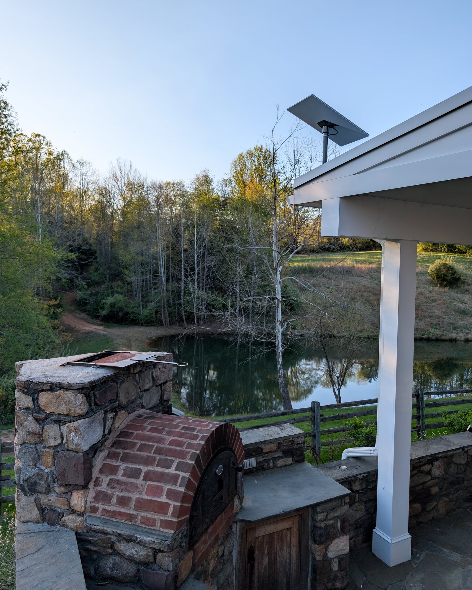
- Internet edge: the provider’s line comes in from the road to the core, and a Starlink dish on the main house is drawn as a backup path; a UPS protects the core.
- Property backbone: buried fiber runs from the core to the guest house, the barn and the office, each with a powered cabinet, because fiber carries data, not power; buried network cable carries data and power to the gate, within its 100 m limit. A point-to-point bridge to the guest house is drawn as a planned second path.
- Coverage and systems: access points in each building and on the terrace, cameras at the main house, office, barn and gate, and coverage zones drawn as intent, not measurement.
- Operations and handoff: every run and cabinet is labeled, and an as-built record of runs, ports and labels leaves with the system.
- Buried fiber · carries data, not power
- Network cable · carries data and power, up to 100 m
- Bridge · a planned second path
- Powered cabinet
- Planned coverage zone
Representative property · not to scale
Four property layers
Layer 1 of 4
Internet edge
Primary and backup paths where the operating requirement justifies them, a managed gateway with documented failover policy, and UPS protection for the core — designed as one continuity decision.
Layer 2 of 4
Property backbone
Fiber where a permanent cable path makes sense, point-to-point bridges where conditions support them, and structured cabling with managed switching inside each building — every route documented.
Layer 3 of 4
Coverage and systems
Indoor and outdoor WiFi planned by use zone; family, guest, building-system, and camera networks kept separate; coverage and roaming verified at commissioning.
Layer 4 of 4
Operations and handoff
Centralized management across the property, equipment and topology records, and credential handoff matched to scope — a system that is owned, understandable, and ready to extend.
Equipment changes over time. The relationships between providers, buildings, coverage zones, power, security, and documentation are what keep the system stable and serviceable. Representative estate layout. Which structures exist, how each one is reached, and where coverage is planned are determined by the property and confirmed on site.
02The property is the system
Complex properties fail at the connections between places and systems.
A main house, guest residence, barn, gate, pool, office, and security system may have been built in different years by different teams — and still have to operate as one property. That takes decisions about provider paths, building-to-building transport, equipment locations, coverage zones, protected power, segmentation, and documentation before any product is selected.
01Structures and distance
Main residences, guest houses, barns, gates, and detached offices need deliberate transport paths rather than signal spillover.
02Materials and terrain
Stone, masonry, mature trees, elevation, finished landscaping, and limited trench routes determine what can be built reliably.
03Services and resilience
Primary and backup internet, routing, protected power, and the network paths for cameras and gates are planned around the consequence of failure.
04Ownership and serviceability
Clear labeling, topology, configuration records, and a commissioned baseline keep the system understandable after turnover.
03Network topology
Multi-building estate network architecture.
One managed core feeds every structure, and how each run is made is a design decision: buried fiber where a permanent path between separately grounded buildings makes sense, buried network cable where the run also has to carry power, an aimed point-to-point bridge where the line of sight supports one. Where the operating requirement justifies it, a second path is planned for a link.
Buried fiber
Carries data, not power.
Buried network cable
Carries data and power, up to 100 m.
Point-to-point bridge
An aimed radio at each end, where the line of sight allows.
04Field record · Castleton, VA
Coverage designed for how the property is actually used.
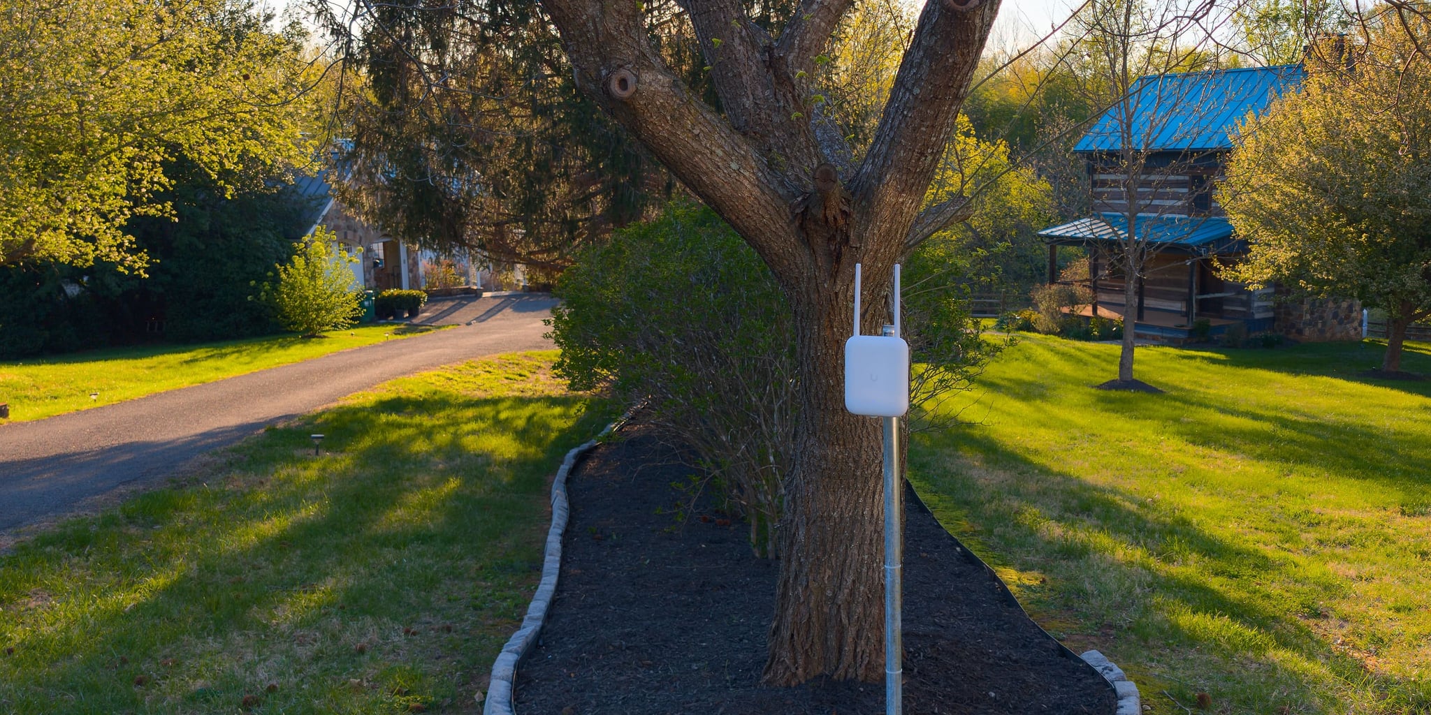
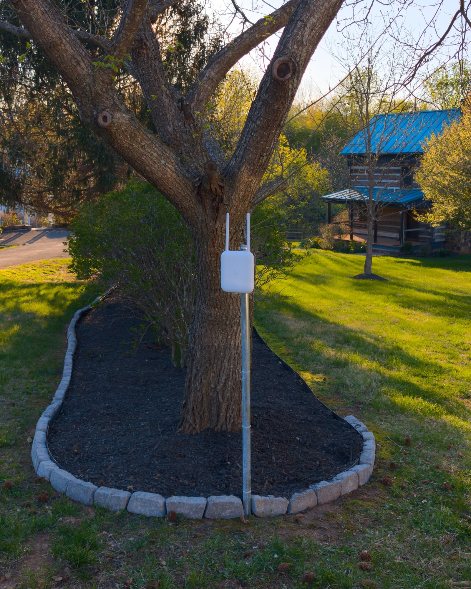
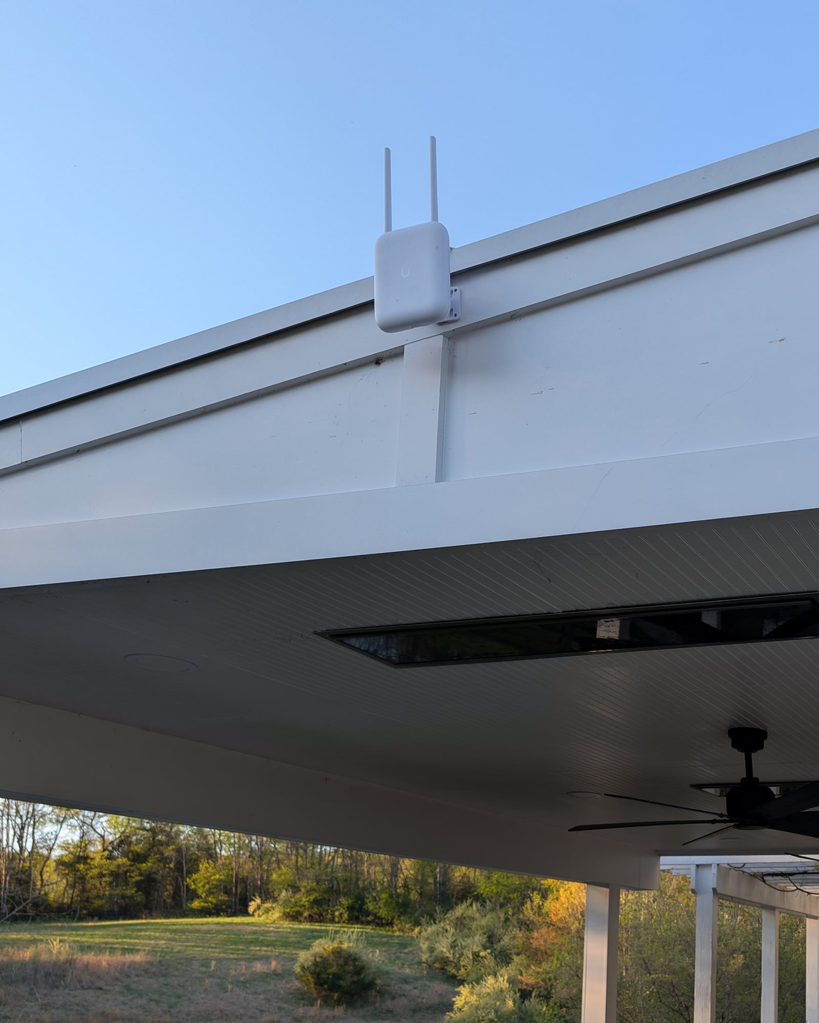
A hunt-country estate where the house, cabin, pavilion, and grounds run on one network — outdoor access points and the Starlink path planned together.
Estate network deployments
Documented multi-structure systems in Virginia.
- Loudoun County, VAHouse and Guest House — PurcellvilleA main house and a short-term-rental guest house on one network, linked by a wireless bridge, with the guests on a network of their own and Starlink with Xfinity as backup.2BuildingsBridgeLink to the guest houseSeparateGuest networkView deployment details
- Castleton, VAHouse, Pavilion, and Cabin — CastletonA main house, a covered pavilion, and a historic log cabin on 2.5 acres, with three Wi-Fi 7 outdoor access points hardwired with Cat6 and one network name across all three.3Structures3Outdoor access points1Network nameView deployment details
05Installation process
From project review to documented handoff.
- 01
Confirm the path
Review before recommendation
The Initial Project Review establishes the property context and whether the next step is a direct quote, an on-site assessment, or an Architecture Plan.
- 02
Diagnose and design
Scope determines the depth
Existing conditions, provider paths, building links, coverage zones, equipment locations, power, and integrations documented before implementation is proposed.
- 03
Build the infrastructure
Scheduled by approved scope
Building links, cabling, rack equipment, and access points installed as one coordinated system, with disruption to household and staff kept low.
- 04
Commission and document
Verified before handoff
Coverage, building links, provider behavior, segmentation, protected power, and management access checked; documentation updated to the finished system.
What you decide
- Where you need service, and who uses each place
- What matters most
- Your budget
- How equipment should look, and how much disruption is acceptable
We recommend the technical design: how each building connects, where equipment goes, and what it takes. You approve it before work starts.
What you keep
- A record of the equipment and connections, so the system can be serviced later
- Labeled cables and recorded routes, matched to the scope of the work
- The main account, in your name. Any support access we keep is a separate account, and you can remove it.
- A record of what was tested: each building link, and backup internet where installed
- Guidance for using the system and adding to it later
06Engagement
The first step should match what is already known.
Estate network projects are priced for the property after the free project review and quoted in writing. The price depends on how many buildings and outdoor areas are included, the distances between them, the route each connection takes, and the equipment. An inquiry does not automatically call for a paid assessment or a full architecture plan: we begin with the property context, then recommend the narrowest appropriate engagement.
For a comprehensive whole-property network, plan for approximately $10,000–$20,000. This is a planning range, not a package price: scope, cable routes, coverage requirements, and backup systems determine the final written quote, which can fall outside it. Targeted improvements are quoted separately.
A strong fit for
- Multiple buildings, outdoor areas, or detached systems that must operate as one property
- Prior installations that left fragmented networks, dead zones, or unclear ownership
- New construction or renovation where cable paths and equipment rooms can be coordinated with the architect and builder
- Provider resilience, protected power, security, and a serviceable handoff all matter
Engagement path
- 01
Initial Project Review
No charge · Non-binding
Confirms fit, property context, and the appropriate next step.
- 02
Direct Quote
For confirmed conditions
Used only when the work is tightly defined and existing conditions are known.
- 03
On-Site Infrastructure Assessment
Approximately 60-90 minutes · Fee confirmed before booking
Paid diagnosis for existing conditions that need on-site review and documented findings.
- 04
Infrastructure Architecture Plan
Scoped and priced for the property
A separate design engagement for complex, phased, renovation, or construction projects.
Also the primary executive office? Dual-provider failover and continuity planning are designed into the estate architecture from the start — see Home-Office Reliability. Not sure which scope fits, start with a Project Review.
07Common questions
Estate network infrastructure FAQ
Yes. Each building usually gets its own link back to the main house, by buried fiber or network cable, or a wireless bridge where digging is not practical, with access points inside. Guests can have a network separate from the family’s.
Not always. Some routes need a trench or a bore under a drive; others can use existing conduit or a wireless bridge. We explain the options and the disruption involved before you approve anything, and the written scope says what digging, if any, is included.
Often. We check its condition and whether it fits the plan. What is in good shape can stay; where something should be replaced, we tell you why.
Yes. Outdoor-rated access points are placed for the areas you use, on the house, another structure, or a post of their own, and coverage is checked at final testing.
Only if something depends on staying online, such as work from home. Backup can be a second internet provider or a satellite service such as Starlink, depending on what is available at the property. When the network switches over, calls and VPN sessions may drop and reconnect.
Eric Enkh reads it and replies himself. He may ask a few questions, then recommends a direct quote, an on-site assessment, or a design plan, whichever fits. The review is free and does not commit you to paid work.
The equipment, and the accounts that run it, in your name: you hold the main account. You also receive a record of the equipment, connections, and cable routes, matched to the scope of the project. Any support access we keep is a separate account, and you can remove it.
Remote support and ongoing maintenance are available selectively for systems we have installed or documented. We discuss what fits when the work is scoped.
08Next step
Tell us about the buildings and what needs to connect.
Share the structures, what is there now, the internet provider, and what has to stay dependable. The Initial Project Review is free and non-binding, and we recommend the next step from there.
The first conversation is free, and Eric Enkh replies personally.