What this report is, and is not
This is a field report: the conditions that come up on Great Falls properties, and what one redesign we documented end to end required. Where a specific condition or result appears below, it comes from the published Great Falls project record. Patterns are described as patterns, without counts.
A correction: an earlier version presented these findings as statistics from fifty networks. Our records could not support that, so it was removed.
Why Great Falls homes are demanding
Great Falls is a demanding environment for a residential network. Large wooded lots, detached amenities, heavy exterior and interior materials, and households that run businesses from home expose weak design assumptions quickly. The common problem is rarely neglect or a lack of spending. It is that the network grew in layers, by different trades, without anyone reducing the property to one system.
Lot scale and detached amenities
Guest houses, gates, barns, pool pavilions, and detached offices are separate network zones whether or not the original design acknowledged them.
Material attenuation
Brick, stone, stucco over lath, metal roofing, low-E glass, and dense mechanical spaces compress real signal behavior well below manufacturer range claims.
Service entry versus core location
Where the provider enters the property usually has little to do with where the network core should live. On a large house that mismatch produces weak backbone geometry.
The expectation level
Work, security, estate operations, and a household of connected devices ride the same system. Reliability expectations are correspondingly higher, and a flicker that would be a nuisance elsewhere ends a client call here.
The documented property is a useful reference point: a residence of more than 4,000 square feet, multiple business operations run from the house, and a household that had already lost a client call to a provider outage. Nothing about it was unusual for the area.
Coverage problems are usually placement and wiring problems
The complaint that brings us to a Great Falls property is most often coverage: the basement gym, the far bedrooms, the patio, the office at the end of the house. The instinct is to add another node. The cause is often that wireless units are relaying to each other through masonry and across long distances, losing speed at each hop, where a cable would carry the connection instead.
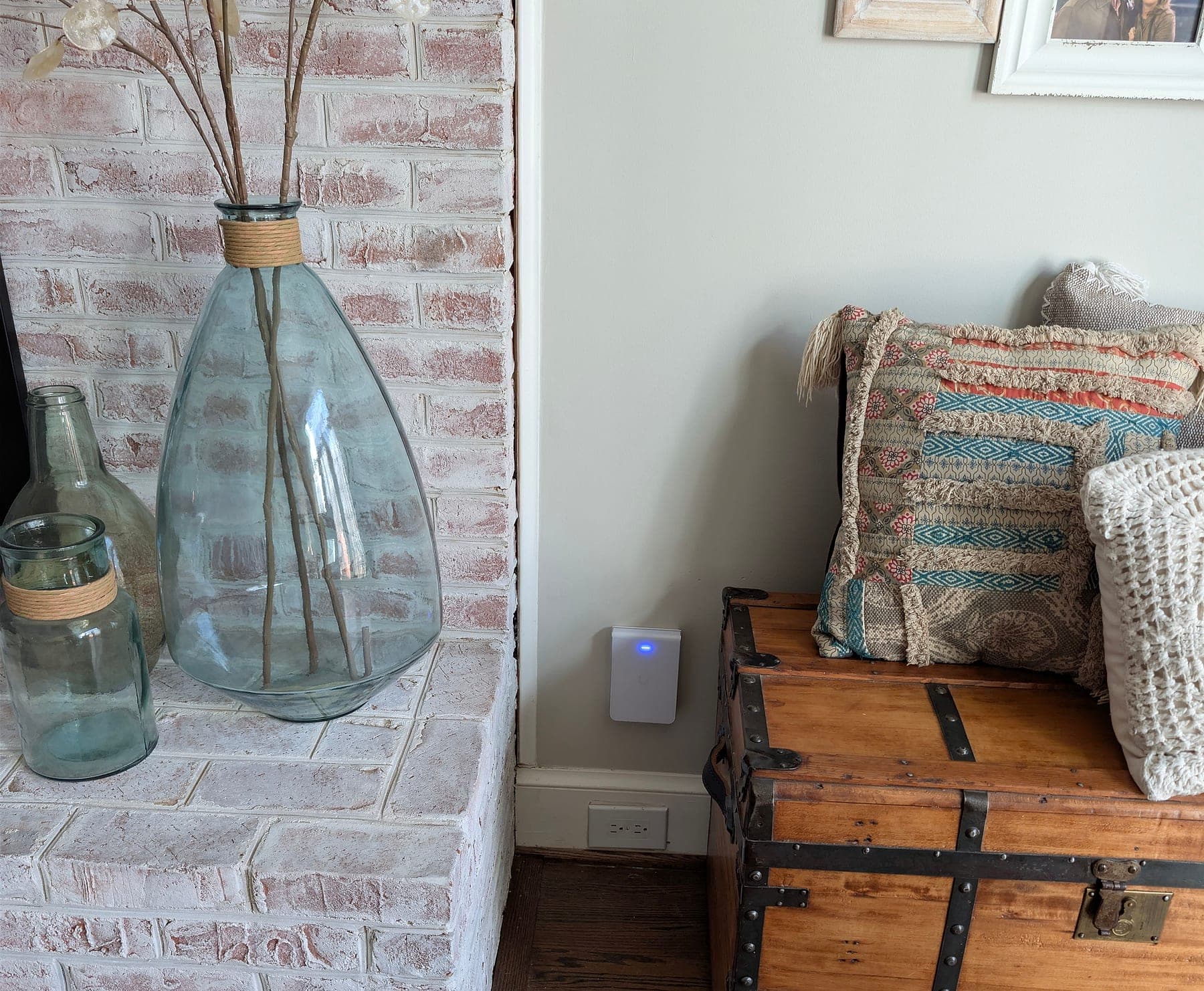
On the documented property, the dead zones were the basement home gym and the second-floor bedrooms, behind a consumer single-provider setup. The correction was not more nodes. It was three WiFi 7 access points placed by zone on wired runs: ceiling units in the second-floor hallway and the finished basement, and a wall-mount unit in the living room. The living-room unit sits beside the brick fireplace mass it has to cover, because placement against the material is the whole point. For a Great Falls home with the same problem, see home networking in Great Falls.
The core is still the provider handoff
The second pattern is a network whose center is whatever the provider installed. Routing, segmentation, and policy are handled by a residential gateway built for light client counts, while automation, guest traffic, cameras, and office sessions are layered on top of it over the years.
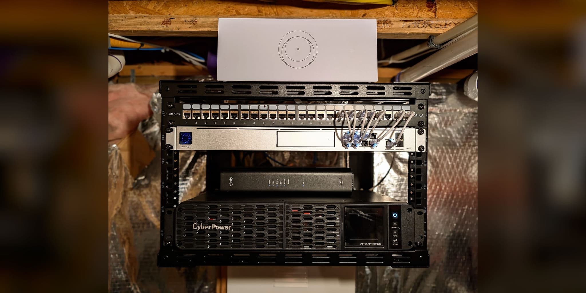
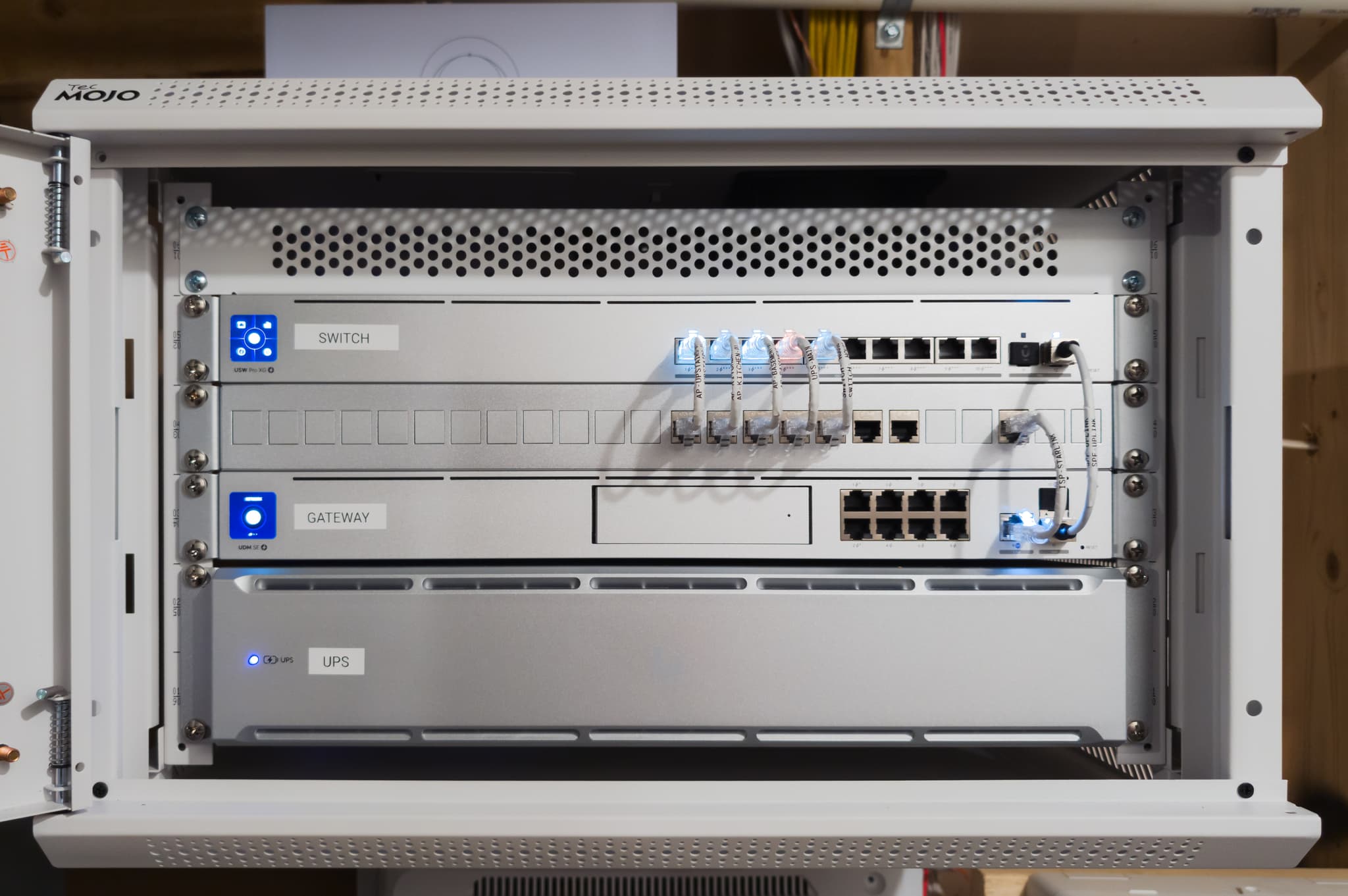
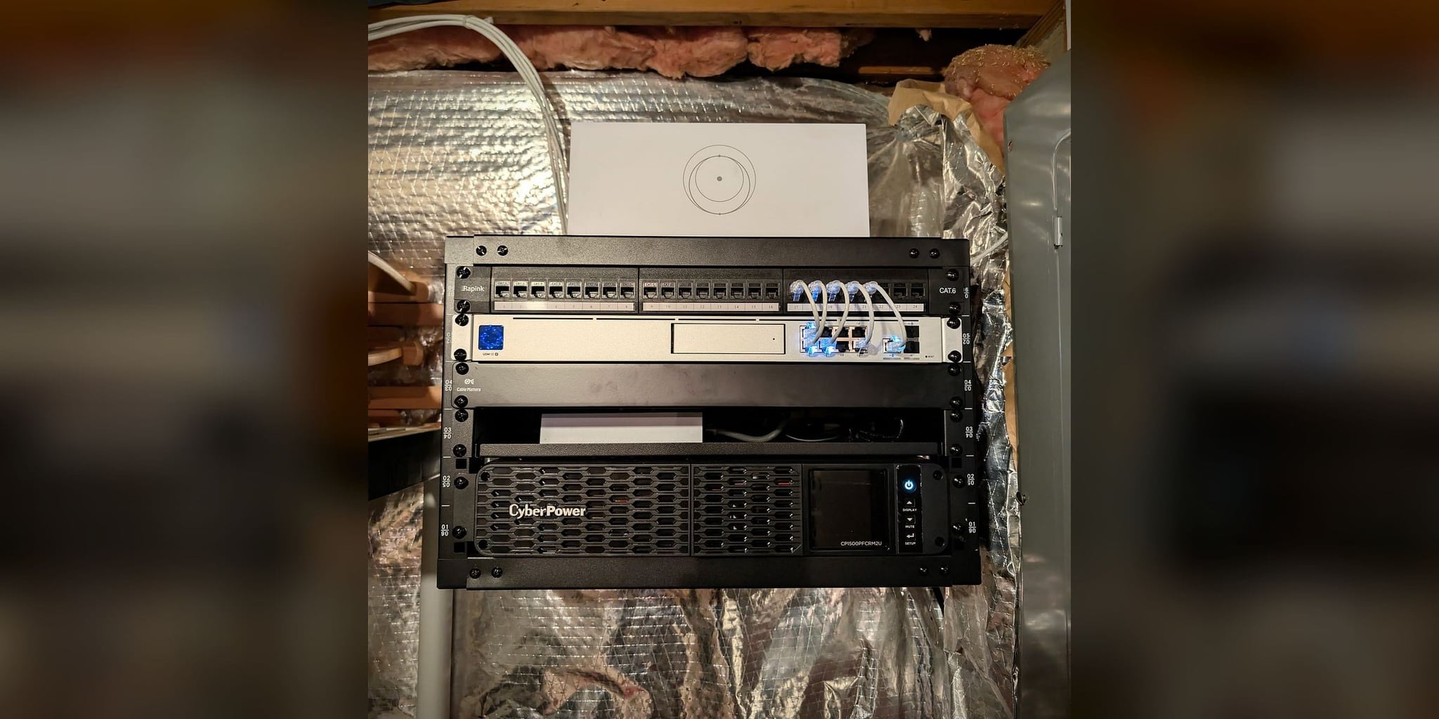
The documented property showed the classic symptom: a consumer router that congested once fifteen or so devices were active, with no visibility into what was happening on the network and no remote way to recover it. The redesign re-centered the network on a UniFi Dream Machine SE in a 6U wall-mount rack in the second-floor office, chosen for proximity to power and to the primary provider entry, with the gateway’s own PoE ports feeding the access points and a dashboard that shows every connected device.
One failure domain for the whole property
The third pattern is the one that turns an inconvenience into an incident. One provider, one router, one power circuit. A Dominion flicker or a Verizon outage does not degrade the network; it removes it, along with the smart-home systems, the cameras, and the call in progress.
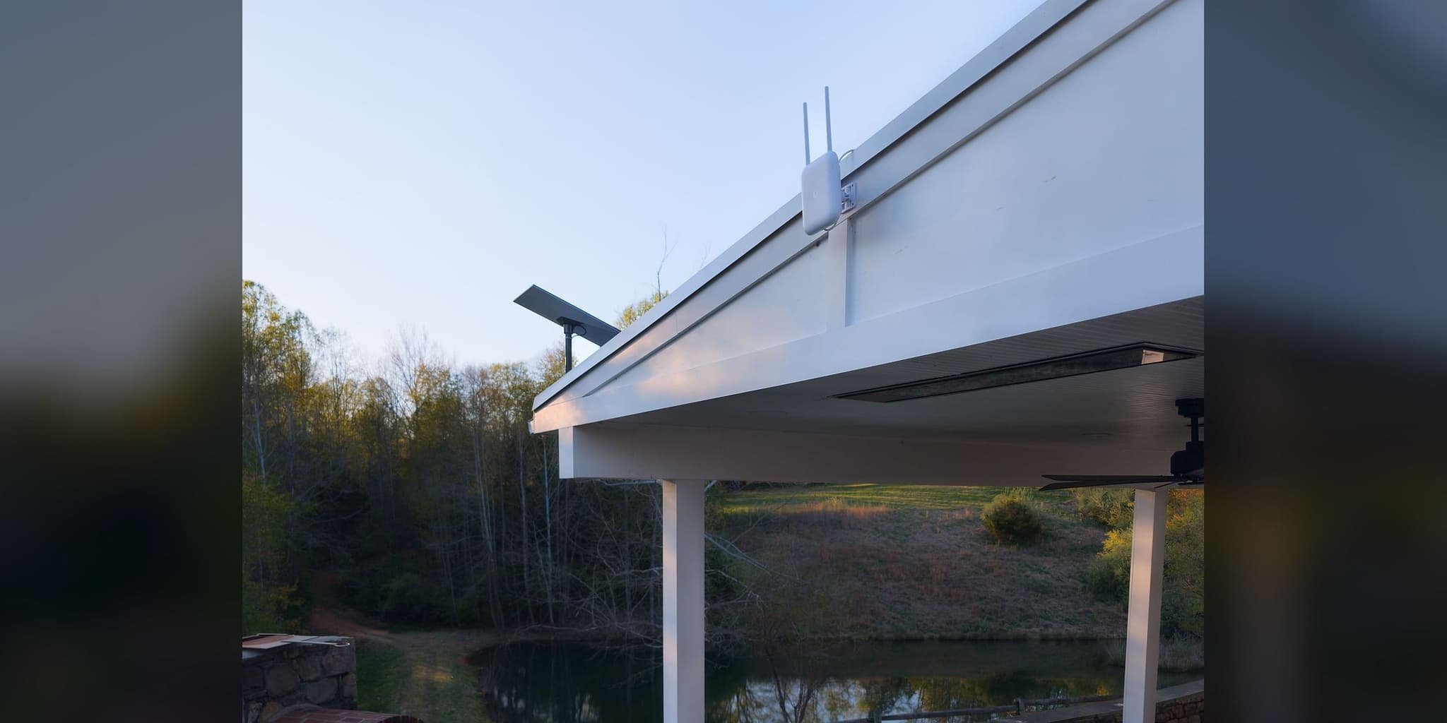
On the documented property that is exactly what had happened. The correction was to narrow the failure domain in two places at once. Verizon Fios stayed as the primary path, with a Starlink Gen 3 dish on the garage roof, positioned for clear sky exposure, as the automatic backup behind the same gateway. And the entire network core went onto a UPS, so a power flicker no longer restarts the network.
At commissioning the primary provider was physically disconnected to test the switchover to Starlink. No switchover time is published for it: none was recorded with a method. A test is an observation on this property’s providers and thresholds, not a promise about a different line.
Dependent systems tied to the provider
The fourth pattern follows from the third. Automation, access, and monitoring are bought as consumer conveniences and depend on a cloud path that disappears with the provider. Once the property is treated as infrastructure, those systems ride a local network that stays up through a provider outage, and security remains locally useful while the outside connection is gone.
This is also where remote management earns its place. With the owner’s permission, the documented system’s status can be checked and its firmware updated without a site visit, which is what keeps a redesigned network from drifting back into the layered, undocumented state it started in. That is access to the system, not a monitoring service.
What the redesign required
Once the causes are clear, the design direction is usually similar from one Great Falls property to the next. The sequence on the documented project was this.
- 01
Re-center the core
A managed gateway with monitoring and policy control, rack-mounted in a serviceable location, replaces the provider gateway as the center of the network.
- 02
Place coverage against the materials
Access point count and position follow attenuation and zone use, checked room by room, rather than equal spacing or ceiling aesthetics.
- 03
Narrow the failure domain
An independent second provider path behind the gateway, and a UPS carrying the core through brief power interruptions, so one failure no longer disables the whole property.
- 04
Commission with a live test
The primary provider is disconnected on purpose, coverage is checked in the rooms that were failing, and the UPS is checked before handoff.
- 05
Document and hand over
An infrastructure guide with equipment inventory, credentials, port map, status indicators, and troubleshooting procedures, plus remote management so the system can be maintained without a site visit.
The outcome was operational rather than dramatic. Failure domains narrowed, coverage became predictable because placement followed the materials, and the network could be managed as one system. The complete record, including equipment, port map, and the commissioning test, is in the Great Falls case study.
When to look at the whole network rather than add another device
Another node, another extender, another provider call: each is reasonable on its own, and each can leave the underlying problem in place. It is worth looking at the network as a whole when two or more of these are true.
- Recent equipment purchases did not solve the coverage problem.
- A detached structure, pool area, or gate needs dependable connectivity.
- Work, telemedicine, or estate security depends on the connection staying up.
- A provider outage or a power flicker takes the whole property offline at once.
- Nobody can say what is connected to what, or how to recover it.
Start with a free project review. Clearly defined work goes to a written quote; when the cause needs diagnosing on site, the paid On-Site Assessment covers that, with its fee confirmed before booking. Properties with several structures are scoped under Estate & Multi-Building Networks; a home office that cannot afford a dropped call is covered in our article on internet failover for home offices.