Loudoun New Construction Estate
New Construction · 10 GbE Backbone · WiFi 7 · Dual-WAN Failover
Complete estate infrastructure for a new construction residence in Loudoun County, Virginia. The system was designed from the input forward — Starlink Gen 3 at the roof peak, a 10 GbE switching backbone, three-zone WiFi 7 coverage, rack-mounted UPS, and dual-WAN failover. Every device is named, labeled, and remotely monitored.
This Loudoun new-construction estate required infrastructure decisions before walls closed. Orbit Tech designed and commissioned a dual-WAN Starlink + primary ISP architecture, 10 GbE UniFi switching core, three-zone WiFi 7 coverage, UPS-protected rack, and full labeling protocol for long-term serviceability.
New Construction Estate Owner · Loudoun County, VA
Timeline: 2 days field execution
Planning began during construction phase
Crew: 1 technician
The Orbit ProtocolThe Scenario
New construction offered a clean slate with one firm constraint: infrastructure decisions had to be made before walls closed. That window is the only time to run cable properly, mount equipment in the right locations, and build a system that behaves as designed for the next decade rather than one that has to be worked around.
Challenge Identified
New construction projects fail at the infrastructure layer when equipment decisions lag behind the build schedule. Cable routes, conduit, and mounting locations are permanent. Getting them right requires making architecture decisions while the building is still open — and then executing cleanly enough that the finished work disappears into the structure.
Solution Design
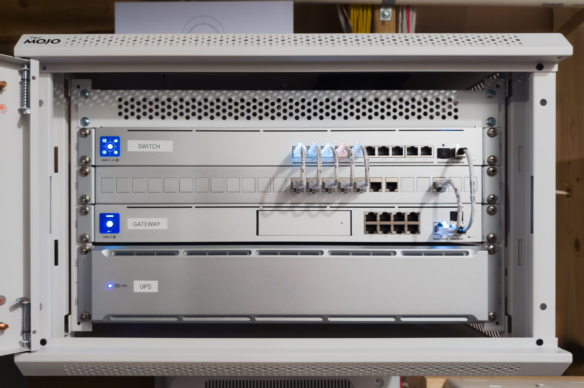
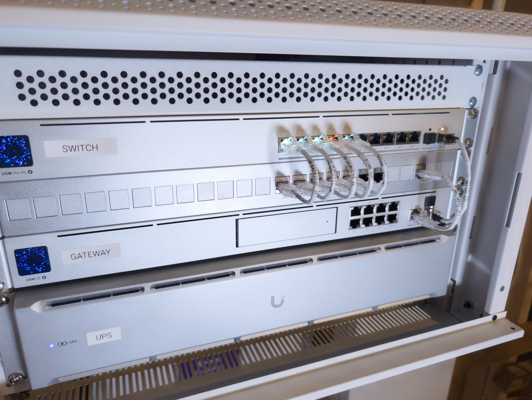
We designed the infrastructure in parallel with the build schedule. Starlink Gen 3 was roof-peak mounted for unobstructed sky exposure. The rack houses a UDM SE gateway, USW Pro XG 10 PoE switch with 10 GbE uplink, and a rack-managed UPS 2U — all wired before the finished surfaces were in place. Three U7 Pro XG and XGS access points cover every floor, including the screened porch, with WiFi 7 performance. Every cable is labeled at termination using a consistent naming convention that appears on the cable, the port, and the controller.
Infrastructure Topology
WAN Failover · Roof Peak
Primary WAN
Core Gateway · Dual-WAN
Network-Managed Backup
10 GbE Distribution
Basement · WiFi 7
Kitchen In-Wall · WiFi 7
Upstairs Hallway · WiFi 7
Dual-WAN estate topology: Starlink Gen 3 and primary ISP feed a UDM SE gateway, protected by UPS backup and distributed through a 10 GbE UniFi switching core to three WiFi 7 access zones.
Deliverables
Quantified Improvement
| Metric | Before | After |
|---|---|---|
| Infrastructure | No network infrastructure (new construction) | Complete estate stack, rack-mounted and documented |
| Connectivity | Single ISP drop, no backup | Dual-WAN with <3s Starlink failover |
| WiFi Coverage | None | WiFi 7 on all floors including screened porch |
| Backbone Speed | N/A | 10 GbE switching backbone |
| Power Resilience | None | Rack-managed UPS 2U for network core |
| Serviceability | N/A | Full labeling protocol — readable without installer present |
Planning a new build or estate network?
The correct time to design cable paths, AP placement, Starlink routing, and rack architecture is before finished surfaces close.
Schedule Infrastructure AssessmentMethodology Applied
Every deployment follows the same four-phase field process so the finished system reflects planning and documentation, not on-site improvisation.
Terrain & RF Survey
Site assessment was conducted during the build window while walls were still accessible. Cable routes, mounting locations, and equipment room placement were confirmed before any finished surfaces were in place. Roof peak sightlines were evaluated for Starlink placement. The design phase began before rough-in was complete.
Architecture Design
Infrastructure architecture was built around permanence. 10 GbE switching backbone, three-zone WiFi 7 coverage mapped to floor plan geometry, rack layout designed for logical organization and future serviceability. Every cable run was planned with a destination label before the first wire was pulled.
Precision Deployment
Two-day field installation. Starlink Gen 3 roof-peak mounted with concealed interior cable path. Rack assembled with UDM SE, USW Pro XG 10, and UPS 2U. Three access points installed and commissioned. All cables labeled at termination matching the port labels on the switch and the device names in the controller. Dual-WAN failover tested before handover.
Sovereignty Transfer
Client received rack documentation, topology diagram, controller credentials, and a walkthrough of failover behavior and remote monitoring. The naming convention was explained so any future service technician can read the rack without relying on prior knowledge of the installation.
Equipment Architecture
UDM-SE
Rack-mounted, dedicated mechanical room
10 GbE uplink
Rack-mounted below UDM SE
WiFi 7 ceiling mount
Basement ceiling, hardwired Cat6a
WiFi 7 in-wall
Kitchen, through-wall fed from rack room
WiFi 7 ceiling mount
Upstairs hallway ceiling, hardwired Cat6a
Standard
Roof peak — unobstructed sky exposure
WAN input
Dual-WAN failover via UDM SE
Network-managed
Rack-mounted, network core circuit
Measurable Results
Six devices online and monitored. Sub-3-second failover between Starlink and primary ISP. WiFi 7 coverage across two floors and outdoor living spaces. A rack that the next installer — or the owner — can read without a phone call.
The documentation was written to be serviceable years from now without the original installer present.
Installation Gallery

Engineering core — every link active, every device monitored remotely
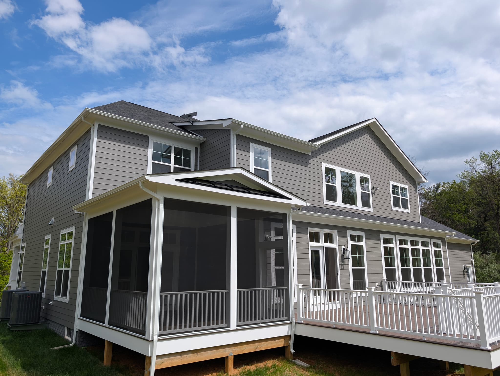
New construction estate — infrastructure planned before walls closed
New construction in Northern Virginia — infrastructure designed from the ground up
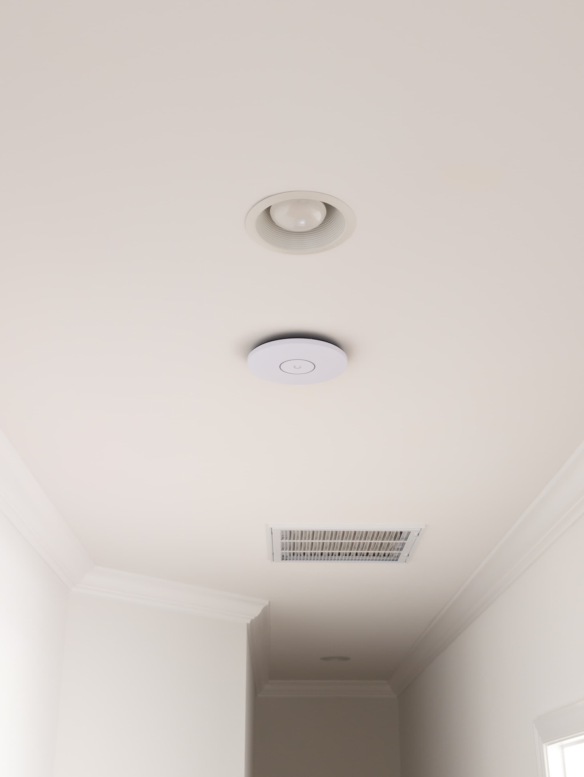
U7 Pro XGS — WiFi 7 with 10 GbE uplink, 500+ client capacity per AP

Every line labeled at termination by destination and device

6 of 6 devices online and named by location — monitored remotely via UniFi controller
This deployment applies architecture documented across our service methodology:
Services Deployed
Equipment Manifest
- UniFi Dream Machine SE (UDM-SE)
- UniFi USW Pro XG 10 PoE
- UniFi U7 Pro XG (basement)
- UniFi U7 Pro XG Wall (kitchen)
- UniFi U7 Pro XGS (upstairs)
- UniFi UPS 2U
- Starlink Gen 3
Related Services
Related Case Studies


Your Property Deserves Engineered Infrastructure
If your property resembles this deployment, the next step is assessing it correctly before more money is spent on disconnected fixes.
Every deployment begins with a property assessment. Tell us how the property is built, where service breaks down, and what has to stay online, and we'll design the system around those facts.