
Campus WiFi 7 Network
5 Buildings • Designed for 200+ Users • Separate Networks
A five-building WiFi 7 deployment designed for density, segmentation, and operational visibility across a campus environment that had outgrown consumer hardware.
At a Glance
- Where
- A five-building campus in Fairfax County, VA, that hosts large events.
- The problem
- Coverage that worked in two of five buildings, consumer access points failing under event load, and one flat network shared by staff, guests, and building systems.
- Constraints
- Five separate buildings, with cabling needed between them.
- What we did
- A UniFi Dream Machine Pro core, 10 Wi-Fi 7 access points, Cat6a between buildings, a guest captive portal, and three VLANs separating staff, guest, and IoT traffic.
- What we observed
- Coverage in all five buildings, staff, guest, and IoT traffic separated, and a design built for 200+ simultaneous users on managed switching.
- How it was checked
- Documented handoff in December 2025.
- Limits of this record
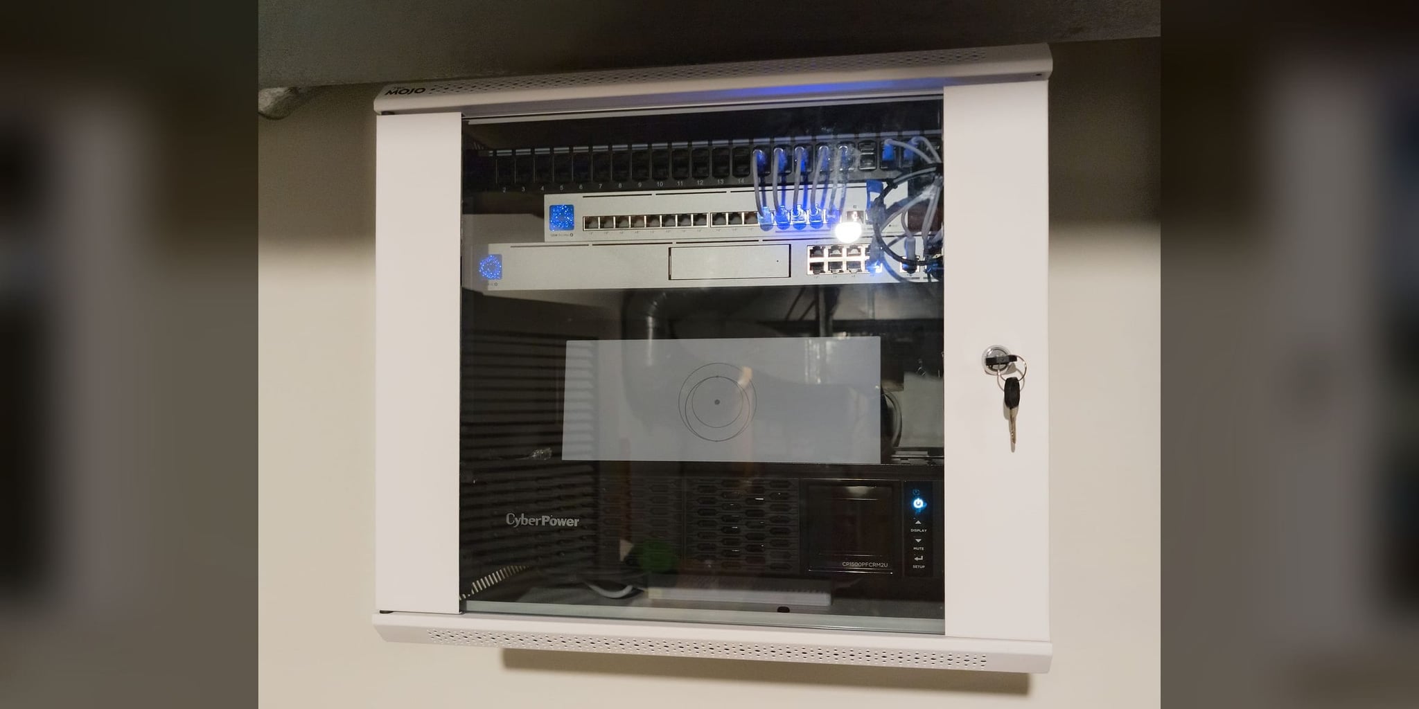
- 200+ users is the capacity the network was designed and built for. The photographs on this page are representative of the equipment, not from this campus.
- Related service
- Whole-Home Wi-Fi · Discuss Your Project
Religious Organization • 5-Building Campus • Designed for 200+ Users
Fairfax County, VA
5 structures
Fairfax County
Timeline: 3 days
The Orbit ProtocolWhat the property needed
The organization was dealing with constant complaints from staff and visitors because the existing wireless network collapsed during large gatherings and offered no separation between administrative users, guest traffic, and building systems.
Five separate buildings had inconsistent coverage, consumer access points were failing under event load, and everything lived on one flat network. That meant poor performance during high-attendance events and unnecessary exposure between staff devices, guest phones, and building systems.
What we did
We rebuilt the campus around a UniFi Dream Machine Pro core, 10 WiFi 7 access points, and a three-VLAN design separating staff, guest, and IoT traffic. Inter-building cabling and centralized management were included so the system could be managed as infrastructure instead of as five separate problem areas.
The Orbit ProtocolHow the project ran, phase by phase
Every project follows the same four steps: look at the property, design, install, then test, explain, and hand over.
Understand the property
Each building was reviewed for RF behavior, construction type, and expected device density, with particular attention to peak attendance periods when the old network consistently failed. Existing hardware, switch paths, and inter-building cable options were documented before redesign.
Recommend a plan
The new architecture separated staff, guest, and IoT traffic into distinct VLANs, with WiFi 7 placement tuned for both normal weekday use and high-density event occupancy. Cabling and dashboard visibility were specified as core requirements, not optional add-ons.
Install with care
The three-day deployment included inter-building Cat6a work, ceiling-mounted AP installation, captive portal configuration for guests, and staged checks of the VLAN policy. Capacity was planned in the design; no load test with 200 users was run.
Test, explain, and hand over
At handoff, staff received dashboard orientation, AP and switch documentation, VLAN mapping, and a clear expansion path for future building or attendance growth. The site moved from unmanaged WiFi complaints to a documented and supportable network.
What changed, and how it was checked
The network is designed for 200+ simultaneous users, staff traffic is isolated from guest usage, IoT devices operate on their own segment, and administrators have real-time visibility across the campus from one dashboard.
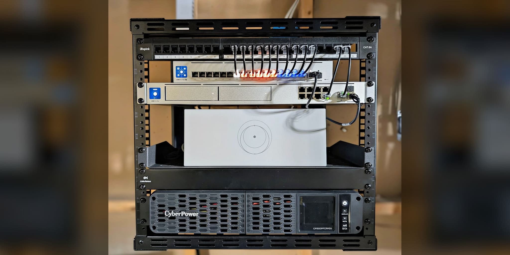
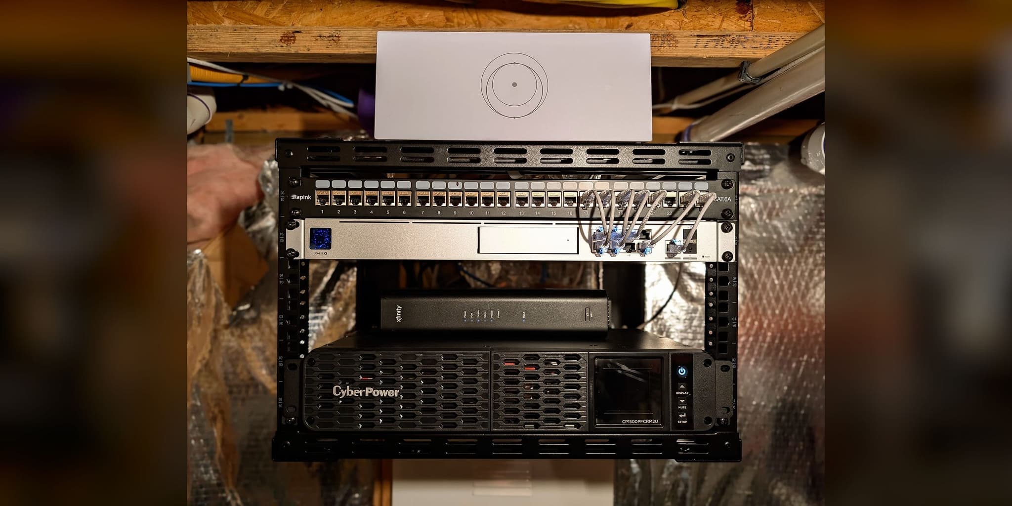
Limits of this record: 200+ users is the capacity the network was designed and built for. The photographs on this page are representative of the equipment, not from this campus.
Before and after
| Metric | Before | After |
|---|---|---|
| User capacity | Failing under event load | Designed for 200+ (design target, not a load test) |
| Network Segmentation | None — single flat network | 3 VLANs (staff/guest/IoT) |
| Building Coverage | Inconsistent, 2 of 5 | Coverage across all 5 buildings |
| Management Visibility | None | Centralized real-time dashboard |
From the installation
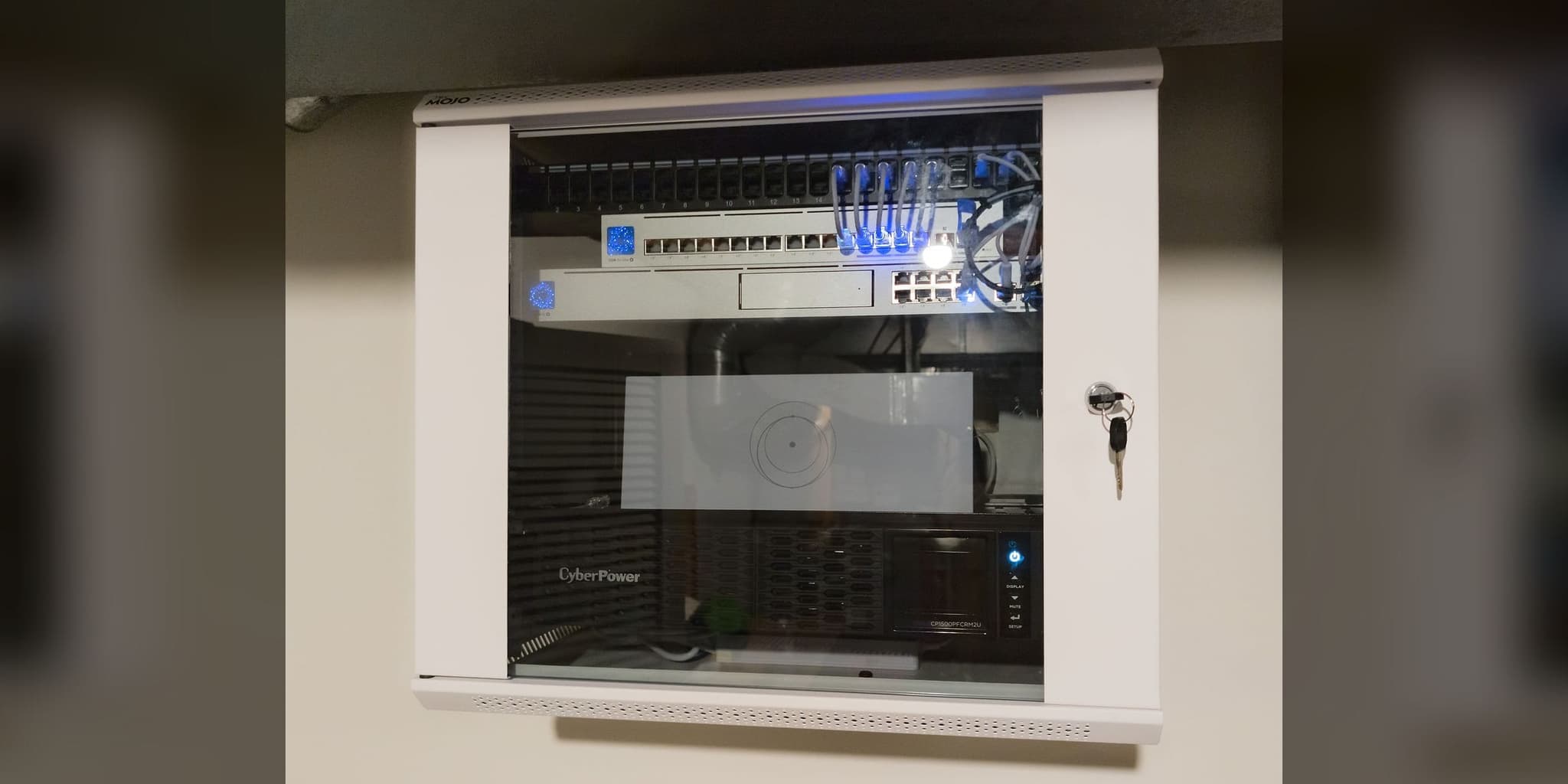
The switching core a five-building deployment depends on
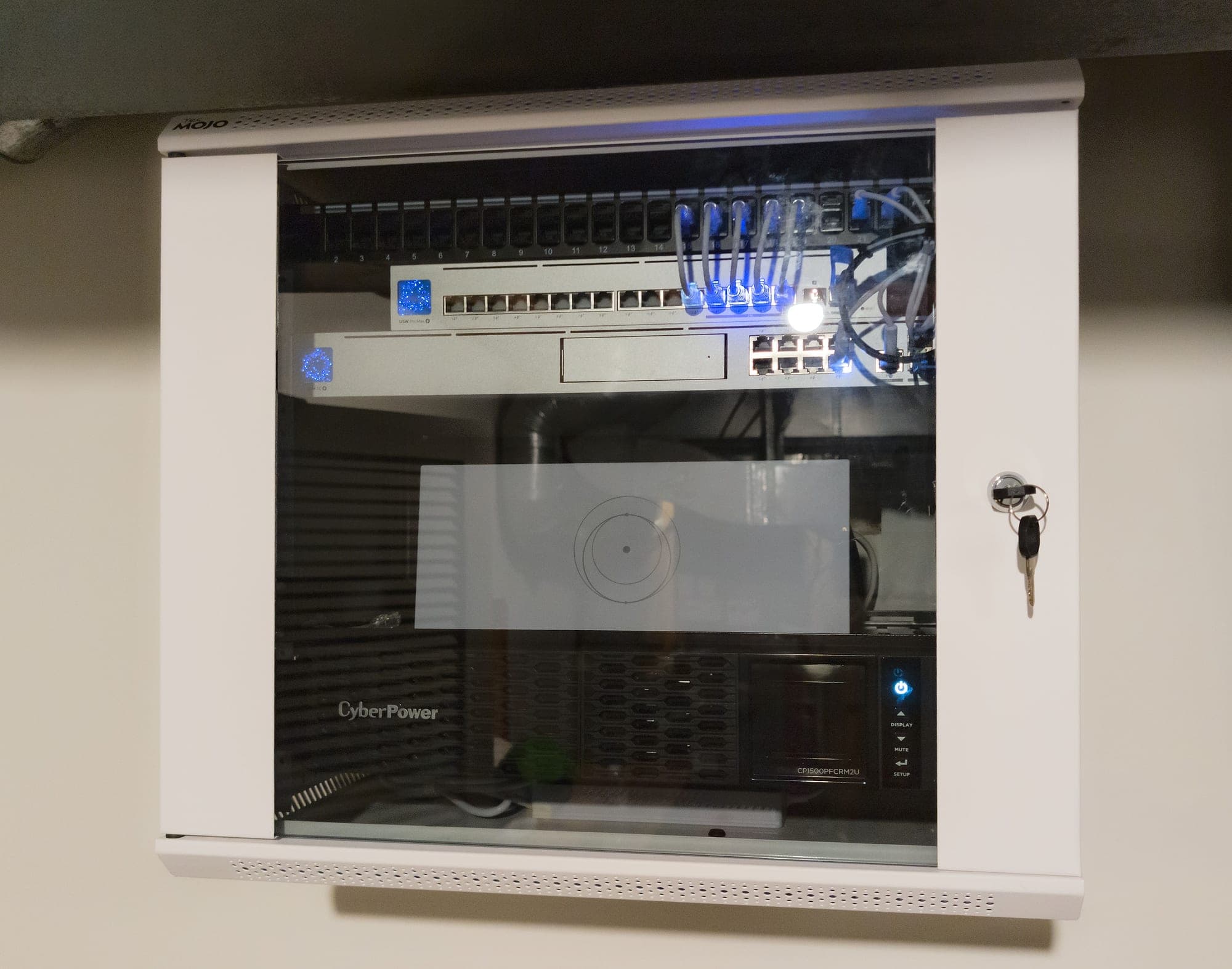
Patch panel, PoE switching, and protected power in one documented location
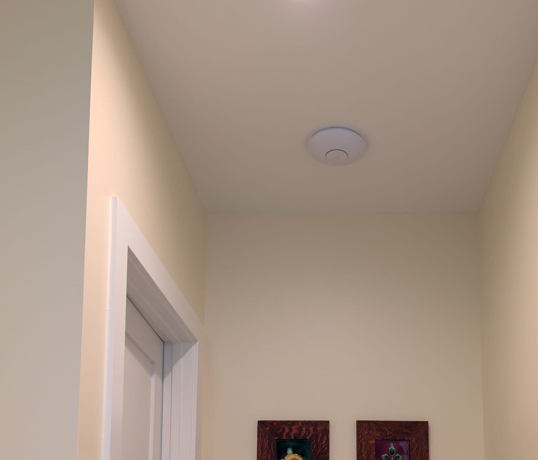
Corridor placement — coverage planned around circulation, not equal spacing
This deployment applies architecture documented across our service methodology:
Services Deployed
Equipment Manifest
- UniFi Dream Machine Pro
- UniFi U7 Pro x10
- UniFi Pro Max 24 PoE x2
- Cat6a inter-building runs
Related Services
Related Case Studies
Planning something similar?
Tell us how the property is built, where service breaks down, and what has to stay online. We'll recommend the next step, and a paid assessment only if the property needs one.
The first conversation is free, and Eric Enkh replies personally.